A table saw or compound miter saw can cut workpieces with two angle settings; bevel and miter. Such a saw is useful when building for example boxes with slanted sides or concrete forms for post caps. It is surprisingly complex to compute compound angle settings. On this page I have collected a few compound angle calculators that will help compute compound angles.
|
|
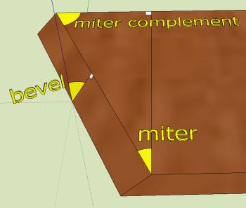
These definitions clarify the concepts discussed on this page.
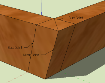
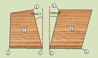
Miter joints and butt joints have identical miter angles; only the bevel angle is different. We can see this in the picture on the right; the cutting lines on the face of the board are parallel.
Angle Precision: Choose the number of decimal digits you would like to round the angle results to.
|
|
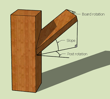
A board with a slope in the long direction intersects a vertical post which is rotated a certain angle.
| Slope angle: | |
| Post rotation angle: | |
| Board rotation angle: |
| Blade tilt: | |
| Miter angle: | |
| Miter complement: | |
| Dihedral angle: |
If your slope or rotation goes in the opposite direction than shown then use a negative angle.
If the board rotation is 0° then the cut can be done without math. Set the blade tilt to the post rotation angle and the miter gauge to the slope angle, then put the board on edge (roll the board 90°) on the saw.
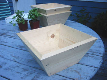
An n-sided box is built from n identical side pieces and a bottom. The box can have sides that are slanted outwards. The outward angle is the side angle.
| Number of sides: | ||
| Side angle (deg): | ||
| Blade tilt, mitered joint: | |
| Blade tilt, butted joint: | |
| Miter angle: | |
| Miter complement: | |
| Dihedral angle: |
Note that this calculator also works for rectangular boxes.
Derivation
 |
 |
An n-sided pyramid is built from n identical triangular side pieces, not including the base. The base radius is the distance from the center of the pyramid's base to one of the base corners. The height is the distance from the center of the base to the apex.
| Number of sides: | |
| Base radius: | |
| Pyramid height: |
| Blade tilt, mitered joint: | |
| Blade tilt, butted joint: | |
| Miter angle: | |
| Miter complement: | |
| Base side: | |
| Side Slope: | |
| Dihedral angle: |
The side slope is measured from horizontal and can be used to calculate any cuts needed at the bottom of the pyramid's sides.
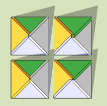
Pyramids with butted joints are some weird animals. A few more or less realistic examples are shown on the right.
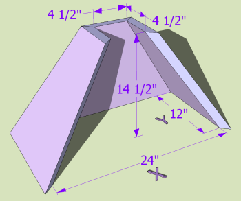
A rectangular pyramid is a pyramid with a rectangular base.
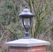
A concrete form for casting post caps can be made in the shape of a pyramid. The pyramid can have a square or rectangular base.
| Base side X: | |
| Base side Y: | |
| Pyramid height: |
| Side: | X | Y |
|---|---|---|
| Blade tilt, mitered joint: | ||
| Blade tilt, butted joint: | ← Same | |
| Miter angle: | ||
| Miter complement: | ||
| Side slope: | ||
| Dihedral angle: | ← Same |
The side slopes are measured from horizontal and can be used to calculate any cuts needed at the base of the pyramid.
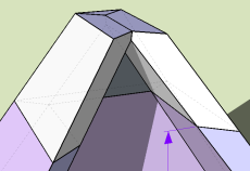
In the case of a concrete form, we need the inside surfaces of the form to line up. In other cases you may want the outside surfaces to line up, but given the same board thickness and a rectangular base, we cannot have both the inside and the outside surfaces line up with this model. For that special case, check out the Rectangular Frustum model below.
 |
 |
In geometry, a frustum is similar to a prism, but the sides are not parallel. This example has a base and a top with different aspect ratios.
| Side: | X | Y |
|---|---|---|
| Base: | ||
| Top: | ||
| Height: | ||
| Side: | X | Y |
|---|---|---|
| Blade tilt, mitered joint: | ← Same | |
| Blade tilt, butted joint: | ← Same | |
| Miter angle: | ||
| Miter complement: | ||
| Side slope: | ||
| Dihedral angle: | ← Same |
The side slopes are measured from horizontal and can be used to calculate any cuts needed at the base and top of the frustum.
Both the inside and outside surfaces line up in this model, on account of the bevel angle being the same for all pieces. This works well as long as there is an opening at the top. Once that opening closes, we must make additional cuts to clear interference between the pieces. The mitered joint Rectangular Pyramid model does not have this limitation. If you want to try this model with a pyramid, set both top dimensions to zero.
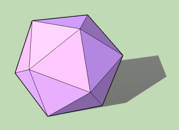 |
The platonic solids is a group of five polyhedra constructed with identical sides.
| Sides | 4 | 6 | 8 | 12 | 20 |
| Name | Tetrahedron | Cube | Octahedron | Dodecahedron | Icosahedron |
| Side shape | Equilateral triangle | Square | Equilateral triangle | Pentagon | Equilateral triangle |
| Blade tilt, mitered joint: | 54.736° | 45° | 35.264° | 31.717° | 20.905° |
| Miter angle: | 30° | 0° | 30° | 18° | 30° |
| Miter complement: | 60° | 90° | 60° | 72° | 60° |
| Dihedral angle: | 70.529° | 90° | 109.471° | 116.565° | 138.190° |
 |
 |
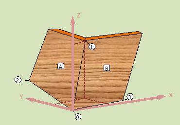
In the general case we have two intersecting surface planes. By defining four points, 0 to 3, on the surfaces in 3D space we can find the miter and bevel angles of sides A and B.
The figure on the right shows the two pieces assembled. The dashed lines show how the XYZ coordinates for point 1 are determined.
Points 0 and 1 lie on the seam between the two surfaces. Point 1 can be located anywhere along that seam except at the origin (point 0).
The line between points 0 and 2 is the reference edge for surface A's miter angle. Point 2 can be located anywhere along that edge except at the origin. Line 0-3 likewise for surface B.
| X | Y | Z | |
|---|---|---|---|
| Point 0: | 0 | 0 | 0 |
| Point 1: | |||
| Point 2: | |||
| Point 3: |
| Side: | A | B |
|---|---|---|
| Blade tilt, mitered joint: | ← Same | |
| Blade tilt, butted joint: | ← Same | |
| Miter angle: | ||
| Miter complement: | ||
| Dihedral angle: | ||
For the mitered joint, for simplicity the blade tilts for pieces A and B are the same, but you can change them as long as their sum is the same. This will affect the intersection of A and B at the top and bottom. For the butted joint the blade tilts must be the same.

Two boards have been joined at arbitrary angles. We orient the joined boards such that their edges are parallel to the horizontal plane. We now specify three angles:
| Angle between the boards in the horizontal plane (deg): | |
| Side angle of board A with respect to horizontal (deg): | |
| Side angle of board B with respect to horizontal (deg): |
| Side: | A | B |
|---|---|---|
| Blade tilt, mitered joint: | ← Same | |
| Blade tilt, butted joint: | ← Same | |
| Miter angle: | ||
| Miter complement: | ||
| Dihedral angle: | ||
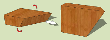 |
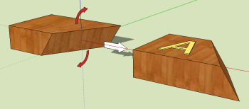
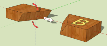
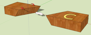
The calculators on this page assume that the boards are laying flat on the saw table. Sometimes we would like to have the board lay with its narrow side down instead. Specifically, we flip the board so that the surface that was facing away from us is now facing up. See the example on the right for how the signs of the angles are defined.
To use this calculator, either first use another calculator above and the inputs will be filled in automatically, or enter values in the input boxes manually. For the simplest case, just one blade tilt and a miter angle are needed.
 |
 |
 |
| Board: | A | B |
|---|---|---|
| Blade tilt, mitered (deg): | ||
| Blade tilt, butted (deg): | ||
| Miter angle (deg): |
| Board: | A | B | |
|---|---|---|---|
| Mitered | Blade tilt: | ||
| Miter angle: | |||
| Miter complement: | |||
| Butted | Blade tilt: | ||
| Miter angle: | |||
| Miter complement: | |||
The following methods may be useful for orienting the board for the compound angles.
 |
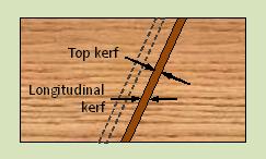 |
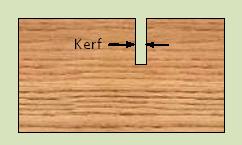
Kerf is the width of the slot cut by the saw blade. When we make a compound cut the width of the slot increases on the surfaces of the board. Bevel affects the width of the top surface slot, while both bevel and miter affect the width of the slot in the longitudinal direction of the board.
If we want to lay out several pieces to be cut on a board, then we need to know the effective longitudinal kerf which will add up considerably over a few workpieces.
| Saw kerf: | |
| Miter (deg): | |
| Bevel (deg): |
| Effective top kerf: | |
| Effective longitudinal kerf: |
|
|

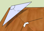 Most of the drawings on this page were created with the 3D drawing program Sketchup. Sketchup is useful for drawing a project and then measure the compound angles. Especially the bevel angle is rather difficult to measure though. Keep in mind that the bevel measurement must be perpendicular to the edge on both surfaces. Draw two short lines to help with the measurement, and check squareness to the edge with the protractor tool (see white squares). You may need to align the axes with the edge. It is very easy to get the bevel measurement off just a little bit by not squaring it up. Move or copy the lines out in the open and draw a line between the end points. This creates a triangle surface on which we can measure the angle between the lines. The bevel angle is then this angle minus 90°.
Credit goes to Chris Glad for being the first to provide an online calculator for butted joints. It is well worth it to check out his calculator.