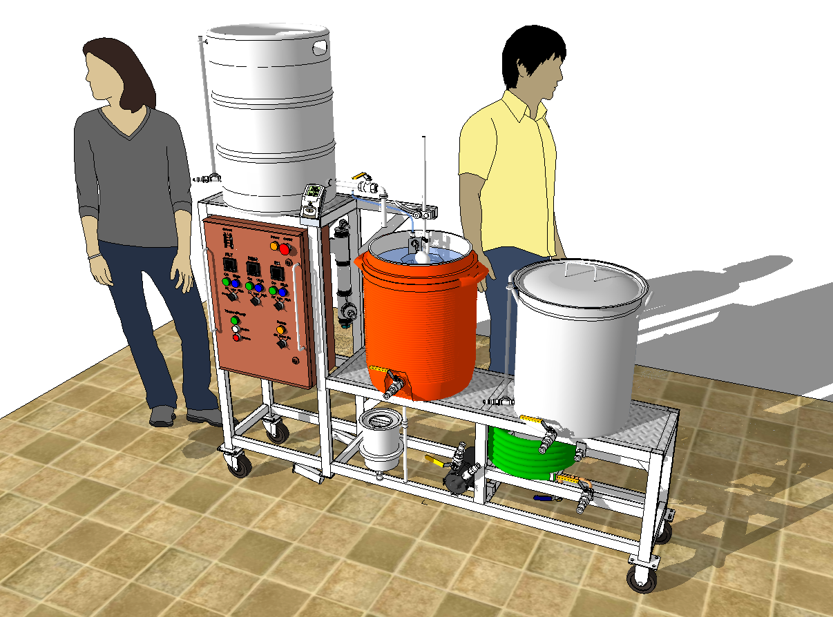
I have been planning an electric all-grain beer brewery to replace my propane heated brewery, which was supplemented with strike water heated on our electric kitchen range. This page collects a few images extracted from the Google Sketchup model I made. I will eventually upload the model to Google when it is finished.
The frame is constructed from 1.5 × 1 × .072 inch steel tubes which will be painted in a silver metallic color. The top of the frame is covered with one foot wide aluminum diamond plate. I will use high-temperature silicone hoses with quick-disconnects to direct the liquids during the brewing processes.
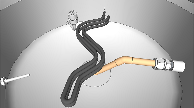
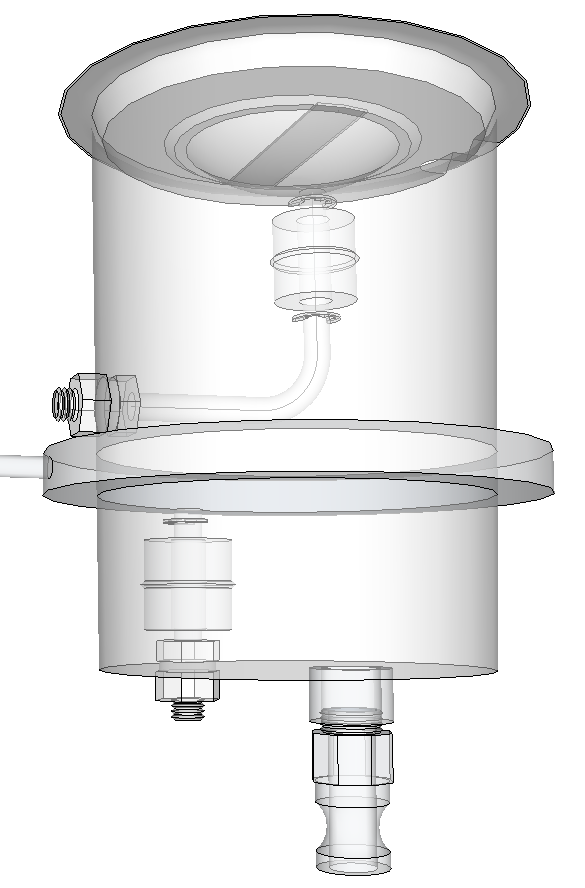
This is a view from inside the Hot Liquor Tun (HLT), which is just a glorified water heater really. Clockwise from left we see an RT100 temperature probe poking through a sight glass fitting. A stainless steel float switch prevents us from dry firing the heater element. A 5500W 240V RIPP Ultra Low Watt Density provides the heat. A 1/2 inch s.s. coupling is soldered to the HLT, and a s.s. compression fitting is threaded into it. A 1/2" dip tube made from copper pipe has a 45° elbow to clear the heater element.
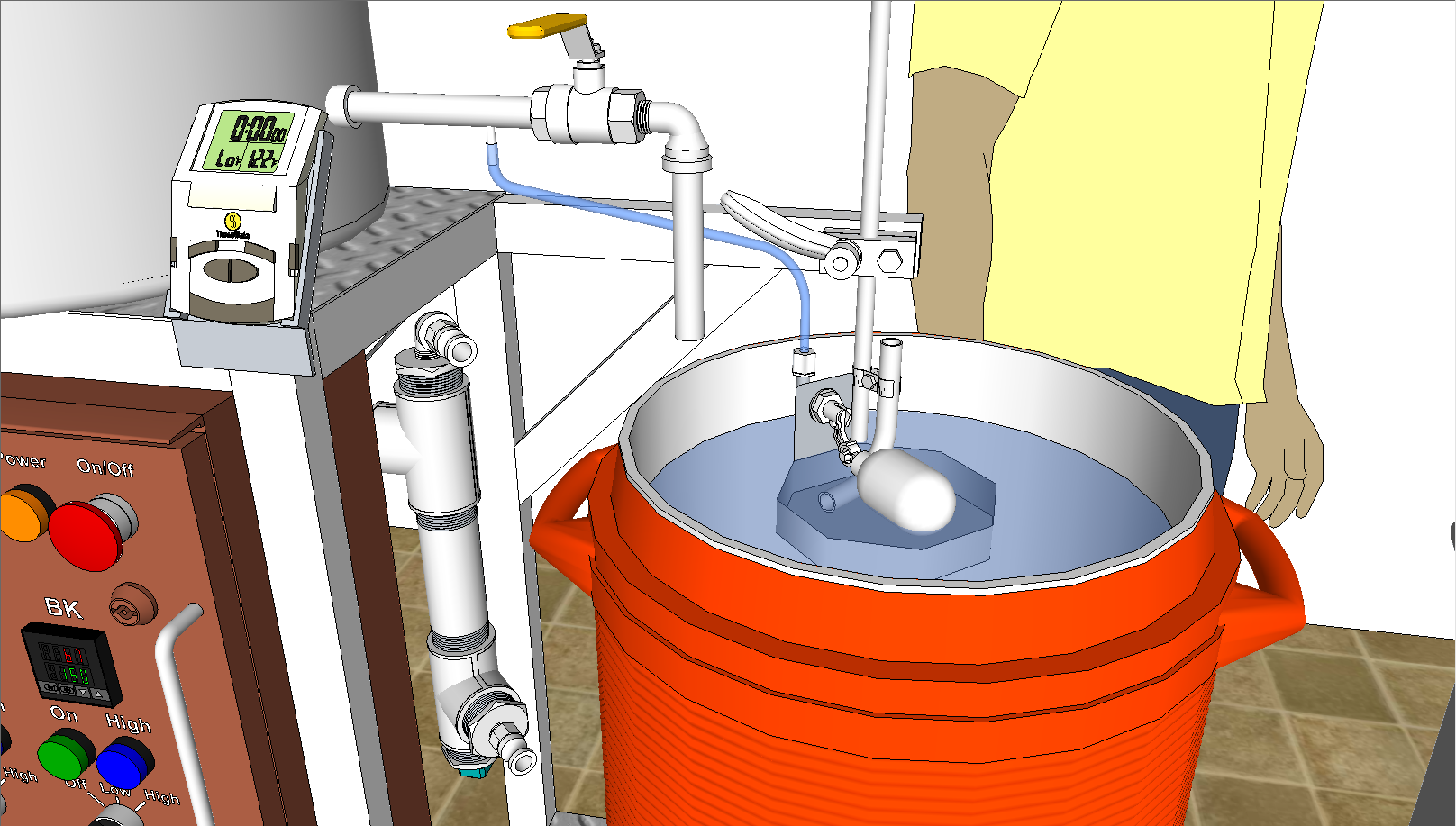
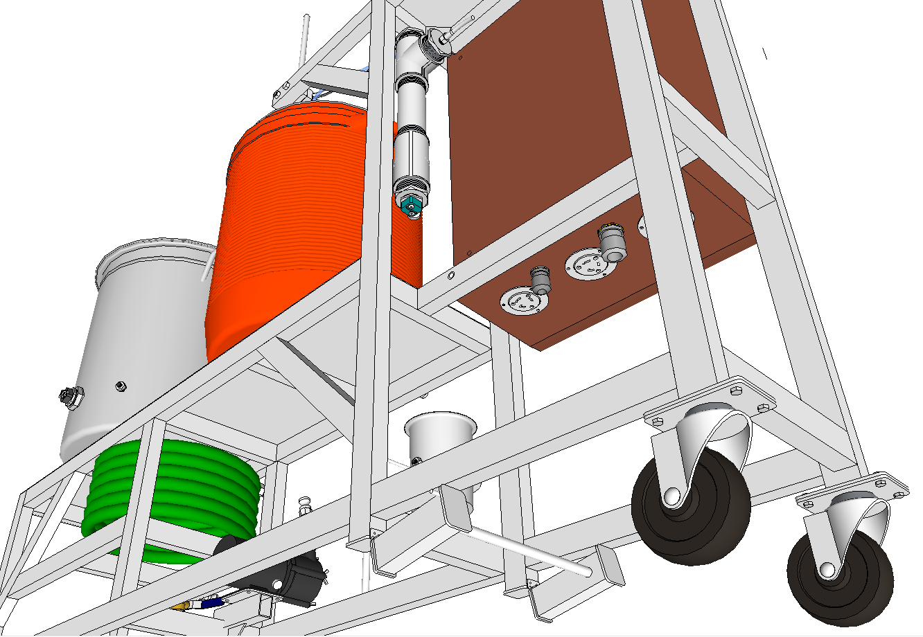
The strike water is drained through the large valve on the HLT into the Mash/Lauter Tun (MLT). The grist will be mixed with the strike water in the MLT, and a pump will circulate the liquid from the bottom of the MLT, through the RIMS tube (seen directly to the left of the MLT) where heat is added if needed, and back to the top of the MLT. During recirculation the RIMS tube will be connected to the bent s.s pipe inside the MLT. An octagonal tray breaks up the water jet and distributes the liquid around the top of the tun. After typically 60 minutes of mashing we start the sparging process where the float valve in the MLT keeps the liquid level constant while we slowly drain the MLT to the grant. This process typically lasts 60 minutes during which the grist is rinsed to extract the dissolved sugars.
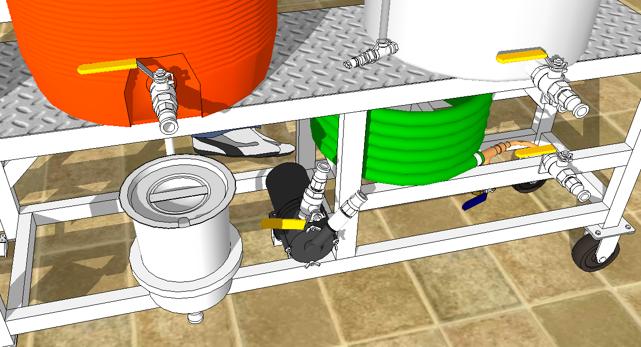
During the sparging process the MLT is slowly drained into the grant (below MLT) where it is temporarily held before the pump moves it to the Boil Kettle (BK). The pump, located to the right of the grant, is a Little Giant model 3 MD-MT-HC with a magnetically coupled impeller. To the right of the pump we can see my homemade Counter Flow Chiller (CFC) which will be used at the end of the boil to cool the wort. It is constructed from 20 feet of 3/8 inch soft copper pipe covered with a garden hose. Wort flows inside the pipe while cold tap water flows between the pipe and the garden hose, extracting heat through the pipe wall.
This is an X-ray view through the grant. A curved float switch starts the pump which will suck wort from the bottom drain of the grant. The pump is held running by a relay until the lower float switch signals that the grant is almost empty, then it stops. The sparge process has only one manual element; setting the flow rate out of the MLT into the grant. The MLT liquid level is held constant by its float valve. The sparge water is held at constant temperature by the HLT heater. The pump moves wort from the grant into the BK as needed.
This is a rear view of the brewery. A set of hinged legs can be swung down to provide extra support of the frame. They also prevent the brewery from moving on its wheels. We can see the outlet jacks for heater elements on the bottom of the control panel, and also cable glands for the input power cable and pump cable. The RIMS tubes' heater element is visible at the bottom of the RIMS tube. Far to the left we see the BK and its heater, and its float switch coming through the kettle wall a little to the right.
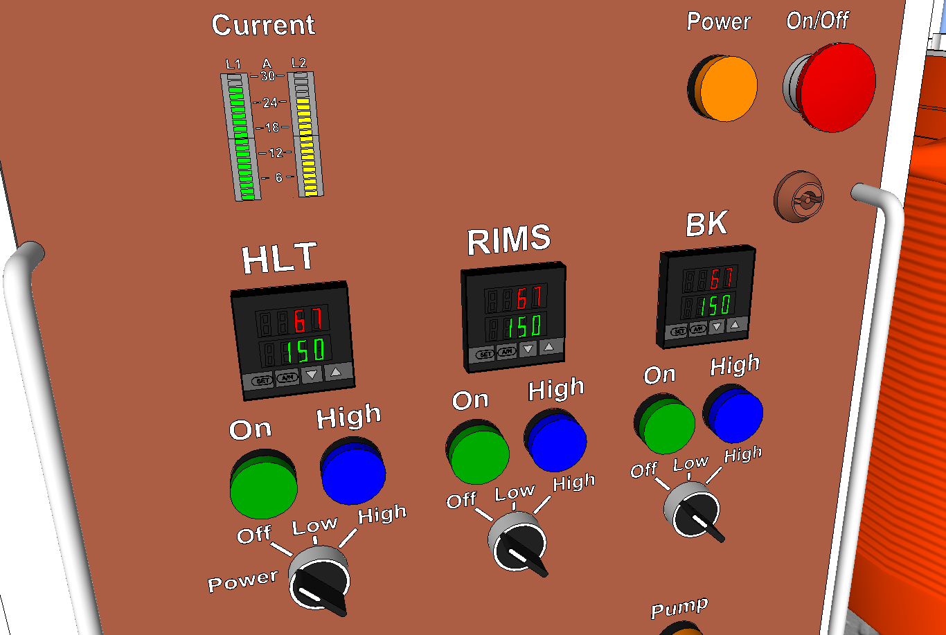
An emergency stop switch is used as an On/Off switch as well. To start the brewery, pull out the E-stop. In the upper left is my custom made ammeter, measuring the total current from the two legs of the electric power. Three PID controllers maintain the set temperatures for the three heated vessels. Each heater has a power switch that can be set to Off, Low, or High. High provides 100% heat by connecting the element to 240V. Low provides 25% heat by connecting the element to 120V. Switch logic inside the panel ensures that the 30 Amp current limit cannot be exceeded by selecting the wrong power combinations. Here is a PDF version of the control panel's wiring diagram.
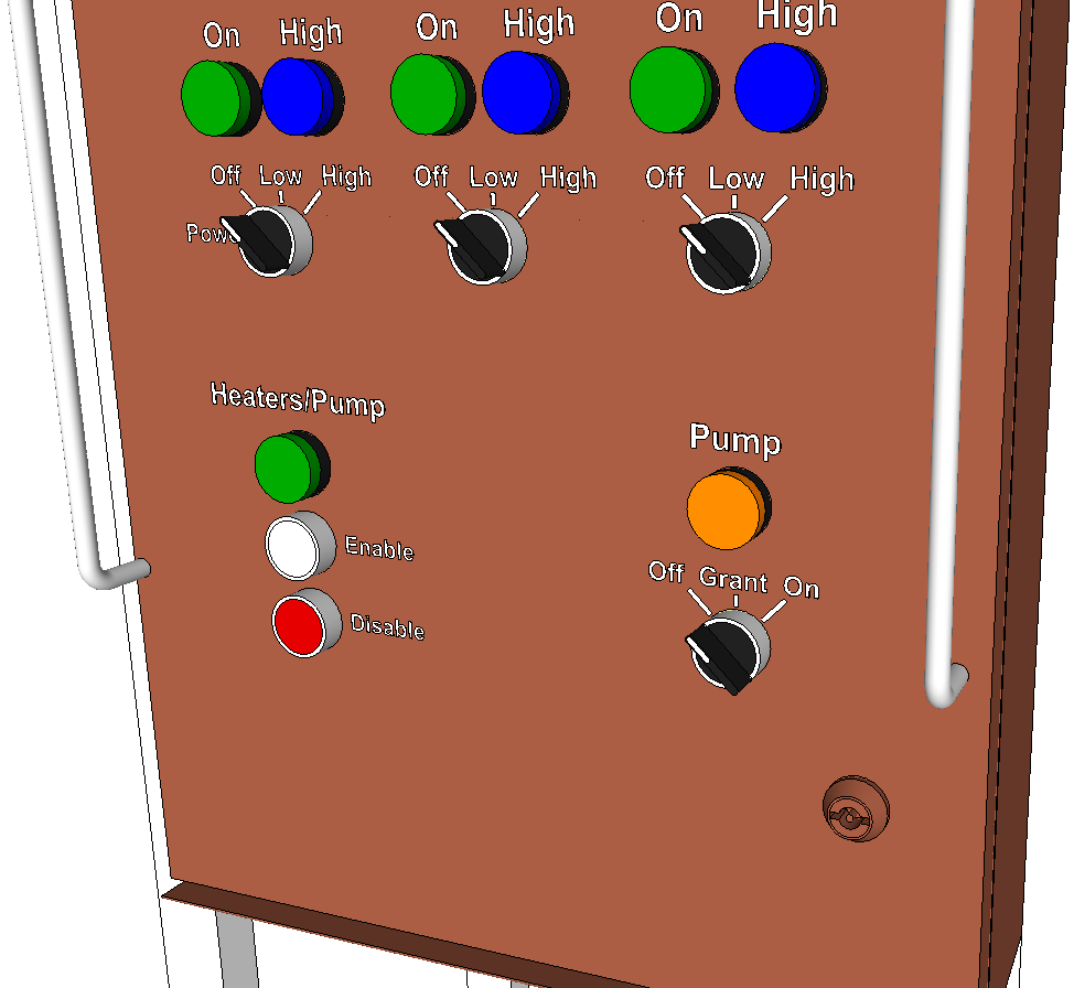
When first powered up the heaters and the pump are disabled. To enable them we need to push the white push button "Enable". The enable button only works if all three power selector switches are set to Off. The reason for this is that if a power outage occurs during brewing, and the power returns a number of hours later, the heaters and the pump should not start, even if their switches are on, because the brewery may be unattended. By forcing the power selectors to be Off to enable, we will prevent any unexpected heating of an element.
With the door open we can see the back control panel which is where relays and contactors are located. At the bottom we see the power jacks for the heaters. Above them is a pair of Hall effect current sensors for the ammeter.
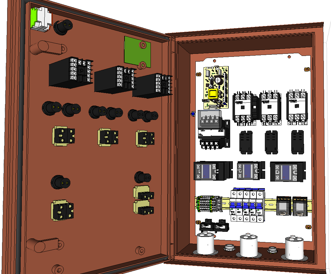
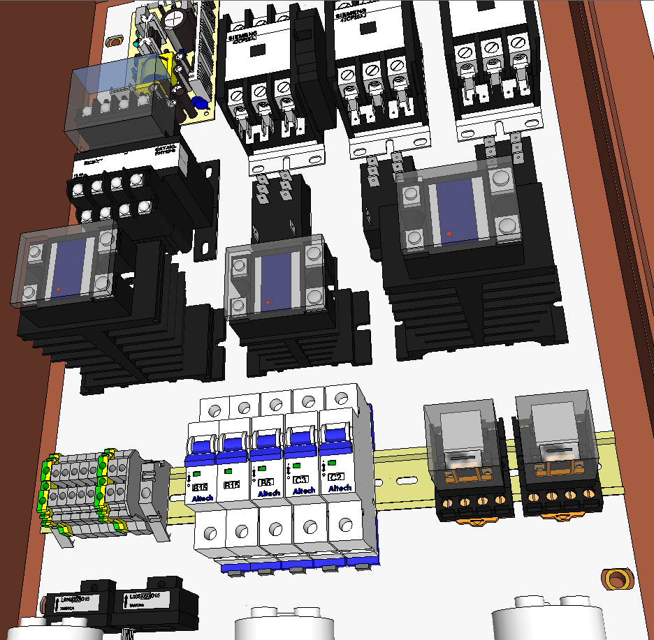
In this close-up we see a 35mm DIN rail which holds a few terminal blocks, circuit breakers, and two DPDT 24VAC relays. All relay coils in this system use 24VAC because some relays are controlled by float switches and it is much safer to operate the float switches with a low voltage rather than the standard 120V. Keeping all controls at one voltage simplifies the system. Above the DIN rail we have three Solid State Relays (SSR) mounted on heat sinks. The PIDs pulse the SSRs to control the heat in each vessel. Above the SSRs we have a 24V 75VA control transformer and three 30 Amp relays. These relays connect the heaters either to 120VAC or 240VAC depending on the power selectors and switch logic. Above the relays are three 50 Amp contactors that can break the power to the three heaters. This is a safety measure so that we can force each heater off in case an SSR has malfunctioned and is holding the power on constantly. In the upper left is a DC power supply providing ±15V and +5V for the current sensors and ammeter.
Comments and suggestions to webmaster@jansson.us